This part of the machining is a pain. The pocket is so deep that the well fills up with chips and needs to be vacuumed frequently.
Machining Parts
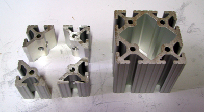
In order to keep the costs of building the CNC router down I decided that I would do my own parts fabrication where I could. Drawings were available on the CNC Router Parts web site in DXF format. I could convert them to gcode for my Sherline 2000. The real trick was to learn enough about machining (ie, being a machinist) as opposed to learning gcode and how to use cad/cam software.
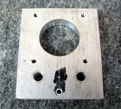
Bearing Blocks: I started out machining the bearing blocks. The principle machining operation is a pocket to hold the bearing and a second pocket to enable the threaded rod to pass thru.
|
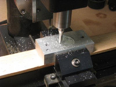
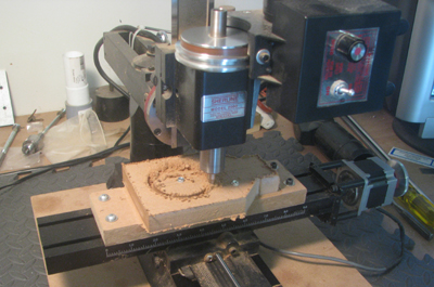
Here is the beginning of the bearing pocket. I've already drilled and tapped the mounting holes for the cover plate. In the lower left corner of the block you can see where I set the z-zero for the cutter. That spot is also my x=.25, y=.25 reference point. More later under "gotcha's" |
|
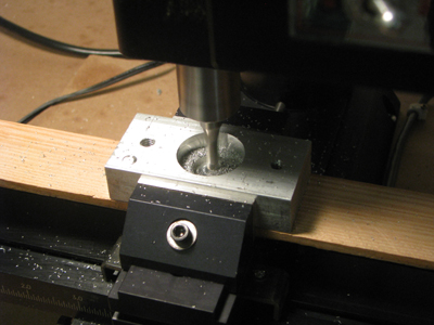
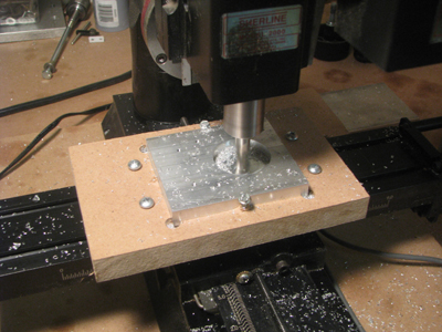
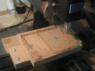
Bearing
pocket finished, now completing the clearance hole for the shaft. The
wooden block will enable me to cut all the way thru the block without
marking up the mill vise. This part of the machining is a pain. The pocket is so deep that the well fills up with chips and needs to be vacuumed frequently. |
|
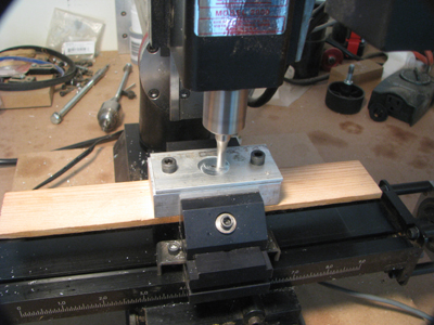
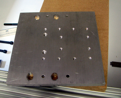
I used one of the bearing blocks as a fixture to machine the covers. Note the edge of the cover is not aligned with the edge of the block. See more under "gotchas" |
Gotcha's
(things I learned by experience...)
1.
I had the metals supplier cut the bearing block to size for me. It was
before I knew how easy it was to cut aluminum on a cross-cut saw. The
result was that I had 5 blocks that were all slightly different sizes.
Same for the cover plates. I used one of the cover plates as a template
to mark an index point (x=.25,y=.25) and the thru holes for the
mounting bolts. Transfer Punches work nicely to do that. The
edges
of the bar stock are slightly rounded so using the corner (x=0,y=0) for
an index would have been a problem. Once all of the blocks were
machined, I made a jig to hold both block and cover while I 'trimmed'
the end of the block in the cross-cut saw.
2. This was the first
serious machining operation I'd done. Getting the mill aligned was my
biggest problem. When I acquired the Sherline, I bought the 2000 series
mill because it offered more 'degrees of freedom' than a conventional
mill. It's possible to rotate the mill head in several directions.
While that's nice, it also means the setup is harder. Setting up the
backlash compensation was also a learning experience. Eventually I
might retrofit anti-backlash nuts to the mill, along with thrust
bearings to protect the stepper motors.
3.
I liked the design of this router because only a few of the components
have critical tolerances. For example, the location of the cover plate
and bearing block mounting screws is not critical. The blocks all mount
in 80/20 slots with some movement. What is critical, is that the
bearing pockets are all in the same places. That's why I used one cover
as a template and transfer punches to duplicate the hole locations. If
you use this method keep in mind that your blocks have a top/bottom
orientation. Mount them all the same way. If they are slightly off at
least they will be consistent.
NEMA23 Motor mounts
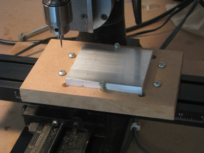 |
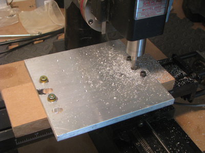
With the experience of the Bearing Blocks behind me I used a different hold down method to machine the N23 mounts. First, I cut the bar stock myself so all three pieces were the same size. Second, they are too big to hold in the sherline vise (the only vise I have for the mill). Like the bearing blocks, the motor mounting hole has to be cut all the way thru the stock. My solution was to use a piece of 3/4 MDF as a work holder. I cut a 1/4 inch pocket in the MDF to hold the stock Since the pocket is cut by the mill, it's automatically aligned with the mill. Also shown is the scribe point held in a 3 jaw chuck that I use as my locater. |
 |
At this point the drill holes have been spotted and the motor mounting hole is being cut. |
 | Gotcha's:
1. Once I mounted a motor in one of these plates I realized that there's no place to attach a strain relief for the motor cable. So I added an extra hole to the design. I like to anchor the cables so that if a cable get's caught somehow you don't rip the wires out of the motor. 2. 20/20 hindsight. If I had this to do again, I might be inclined to machine this as a 2.5D profile instead of a pocket. Pocketing removes all the material on the inside of the pocket. That's a lot of aluminum. A 2.5D profile would cut out a plug. But that would require me to drill and anchor the plug somehow or it could potentially jam when cut free. |
Z Axis Mounting Plate
 |
Like the NEMA 23 Motor mounts, the Z Axis Mounting Plate was a problem because of it's size. Even though the Sherline 2000 has 7.5 inches of Y-axis travel, there's only 5.25 inches of clearance between the spindle center and the column support. In this case I was lucky, there are no machined features on the forward edge of the plate. |
 | Gotcha's: After mounting the Z-Plate on it's slides and attaching the Bosch Colt mount (with the Colt in it). (see Assembly pix) I decided that the Colt was too close to the work surface. So I added a second set of mounting holes. This gives me a low/medium/high set of mounting positions for more flexibility. |
Angle Brackets
 | The latest version (ver 4) of the router design now includes angle brackets. I had not bought any from 80/20 and they are a rather pricey component. However, since my piece of 3030 was longer than I needed the leftover piece provided me with material to make mu own angle brackets. I cut a piece of 3030 to 1.5 inches and then drilled it. Then I cut it into quarters which make nice angle brackets. |
Bosch
Colt Router Mount
I
was originally planning on buying a mount for the Bosch Colt trim
router that I bought for this project. However a friend posted .dxf
drawings for one so I thought I'd try my hand at making my own first.
 Here the outer edges of the raw blank have already been machined away and I'm cutting the mounting hole for the router. Note the screw that's holding down the center part of the circle to keep it from coming loose at the end of the cut. |
 This is the back of the mount. The part that attaches to the Z axis plate. The pocket has already been cut and the outer edges are being trimmed off. |
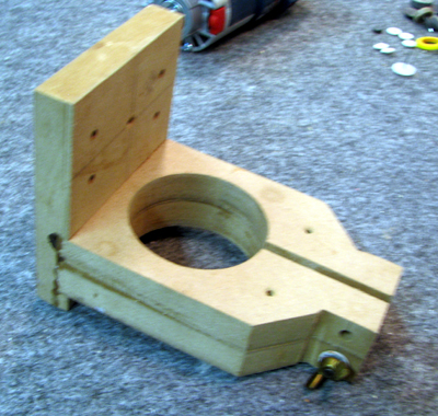 |
Here is the mount glued together. You
can see it with the router installed in the assembly section. Consider
this as version 1. Based on some postings on the firball cnc forum I'm
going to add a dust collection fixture to the mount. |
| Design Tradeoffs |
Home | Cutting, Drilling & Tapping |